Hunter Kirkland was an intern at Fat Pencil Studio in 2016.
Profile Builder 2 brands itself as "light speed modeling of smart building materials using parametric profiles and assemblies" that is able to "build, edit, and qualify intelligent models of real building materials," meaning it is capable of parametric design along a path and has the ability to quantify the components. This is achieved through a fairly straightforward interface that is split into three main parts: profiles, components, and assemblies.
- A profile is basically the typical Follow Me tool idea of a shape extruded along a path.
- A component is something that can be repeated along that same path.
- An assembly is when the two are combined.
If you visit Profile Builder in the SketchUp extension warehouse, you'll find a ton of profiles available (things like typical steel and wood sections). Even some assemblies are free too load (railing system, spiral stairs, railroads, etc.) What makes the extension fun, however, is the fact that it's completely customizable! You can create your own profiles and components within SketchUp, or download them from 3D Warehouse, which can then be used in assemblies you can create with Profile Builder 2. This allows for unlimited exploration as you also control the position, frequency and spacing of components.
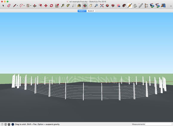
Below, I've outlined a couple of simple but effective assemblies I was able to come up with. With some tweaks and improvements, they could become incredibly useful, versatile tools. The first is the rail assembly. Rails, in my opinion, are the easiest to create using Profile Builder 2.
EXPERIMENT 1

STEP 1:
Create or download your vertical components.
NOTE: Make sure that you are using a component, not just a group! If not, you will not be allowed to load it into an assembly.
You can take this time to create your profiles as well if you don't wish to use a standard profile.

STEP 2:
Open the assembly dialogue, click "select from model", then select your component. Make sure your component is oriented correctly (up is up). Right click the component and select "change axis".
NOTE: The steps are the similar for loading and using a profile; select the profile tab, select your profile face and then hit the "+". You can name assemblies you've made and reuse them.
STEP 3:
Now you have a component and a profile in the assembly, you can use the parameters in the dialogue box to arrange them. This can get tricky and I recommend hitting the button in the bottom right to test a stretch of your assembly. Any time you make changes you can hit the third button in that sequence (the one with a green check) and it will update any assemblies you have selected.

STEP 4:
Repeat while adding desired components and profiles (in this case, I added more profiles adjusting the elevation and you'll have the number of safety cables you need. Again, everything is customizable and you can cycle through a lot of iterations quickly by adjusting your parameters and using the green check button to update your built assemblies.
NOTE: Checking the "max" box when setting the parameters for your component spacing will ensure exact spacing. If this box is unchecked, Profile Builder will adjust the components to fit the line while staying close to the desired spacing.
You now have a parametric rail assembly! Save it and use it over and over.

STEP 5:
I wanted to touch on one more feature of Profile Builder 2 that pairs nicely with the rail assembly: the Smart-Path Select tool. This tool selects a complex series of connected edges; for example, I created a bit of topography and projected a circle onto it.

STEP 6:
To get your assembly-edges combo to follow a complex series of connected edges, choose the Smart-Path Select tool, then click on the complex edges. I often find it easiest to double click instead, which instructs the extension to extrapolate and guess the edges you want selected. If your complex edges are connected to others you aren't looking to select, you can simply click the first edge and then follow the path you'd like.

STEP 7:
Once you have your path selected, simply click the button to the right the assembly button. This will fit your assembly along the complex edge.
EXPERIMENT 2
After learning the basics of Profile Builder 2, Joshua challenged me to use the same process to generate parametric city blocks in one click. Well, it takes more than one click, but its still pretty quick.

STEP 1:
Create a corner condition, a curb cut, or bulb out. Again, make sure that you are using a component, if not, you will not be allowed to load it into an assembly! You can take this time to create your sidewalk profiles as well.
STEP 2:
Open the assembly dialogue, click "select from model" then select your corner component. Again, select "change axis" to make sure your component is oriented correctly.

STEP 3:
When looking at your component, uncheck the "infill" box and check the "start" box. The preview should make more sense now. In my case, I had to offset the component the width of the sidewalk and rotate it to face the street; proper axis placement will avoid this.

STEP 4:
Using the preview window, adjust the parameters so the component and the profile are aligned. Be sure to have the axis on the inside edge of the assembly and that the curb cut is not the starting point. These parameters will change depending on the dimensions of your corner condition and sidewalk. For the assembly to be effective, it must create the sidewalk on the outside of the the line you draw. The corner condition should not be the starting point, the profile or back edge of the corner condition should be the assembly's starting point. You can use the start and end setback parameters to ensure these conditions.

STEP 5:
This is a basic sidewalk assembly! Save it and use it over and over. To make a full city block, follow all four sides. You can add components such as trees, benches, and recycling bins from the 3D Warehouse, or create your own.
STEP 6:
Load your favorite tree component or make a new one. Add it into the assembly and adjust the start and end set back to keep avoid the corners. Adjust the spacing to your desired dimensions. Voila, street trees!


STEP 7:
Find, load, and adjust the parameters for any other components you want to include - benches, recycling, waste bins, signage, or lights even!


If you're interested in exploring Profile Builder 2 even more, check out this handy manual.